Causes of excessive consumable wear.
No, TIG Torch requires a gas valve with connection to shielding gas regulator.
No, The 160S does not have remote control functions.
A optional TIG Torch is available with standard off the shelve 10N series consumables. See Brochure for details. You can also use any Air Cooled TIG Torch that has a Dinse 50mm power plug and gas valve.
115vac and 230vac Single Phase.
Yes, For an explanation of PFC see FAQ Support Topic “Power Factor Correction – What is it? Why is it required? How is it Achieved?”
Yes, you can run 6010 electrodes.
A TIG Torch is included with standard off the shelve 10N series consumables with remote torch controls. You can also use any Air Cooled TIG Torch that has a Dinse 50mm power plug.
115vac and 230vac Single Phase.
Yes, For an explanation of PFC see FAQ Support Topic “Power Factor Correction – What is it? Why is it required? How is it Achieved?”
It comes down to cost. To run E6010 electrodes must have a big inductor and suitable software. This added circuitry is needed because E6010 does not contain potassium in the flux. Potassium helps to stabilize the arc. It will run E6011 just fine.
Yes, the Sanarg 180AP does have High Frequency start.
Generator power vs mains power
Compared to mains power, generator power can be characteristically ‘dirty’ and thus has the potential to damage sensitive electronic components inside inverter welding machines. This is especially the case with smaller generator sets that are often chosen for operating the likes of power tools and welders, due to their portability and affordability.
At the same time, the ability to use generator power offers many advantages to operators wanting to run their inverter welding machines in the field or on-site where it is impossible or difficult to access mains power.
So, it is no surprise that one of the first questions operators ask before they consider purchasing an inverter welding machine is: “is it safe to run off a generator?”. The truthful answer is not always a “yes”. Sure, plug virtually any inverter welder into a generator and it will likely operate to some level. But not all generators are created equal and have clean power.
Why is generator power potentially harmful?
AC (mains) power supply follows a pattern called a sine wave. When it comes to running equipment with sensitive electronics (like inverter machines and computers) power supply with a perfectly clean sine wave is the safest, however in reality this is almost impossible to achieve.
A perfectly ‘clean’ 240V single phase AC sine wave would look something like this:
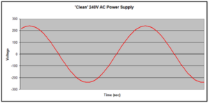
Mains power is (usually) relatively close to perfect sine power and therefore it rarely poses any problems.
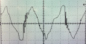
On the other hand, power supply from a portable generator is, by comparison, typically ‘dirty’. The peaks, troughs and cycle frequency will not be consistent even though the average output power may still read 240V on a simple measuring device like a multimeter. Generator power can also be characterized by voltage ‘surges’ (a rise in voltage) and voltage ‘spikes’ (very sudden peaks of excessive voltage).
In a generator, voltage surges and spikes can occur due to several reasons, including:
A typical generator with a high THD over 6% would look something like this. This is NOT a generator you would want to operate your welding equipment, computer, etc. with.
Why are inverter welders vulnerable?
To significantly reduce the size of the transformer and achieve the many advantages that the inverter gives us (reduced size/weight, etc), the input power must be ‘treated’ before it enters the transformer – in other words instead of immediately passing through the transformer, it first passes through sensitive electronic components.
The main components of concern are capacitors. Capacitors are devices which constantly charge and discharge voltages. In an inverter welder, the capacitors will charge at approximately 1.4 times the standard input voltage. So, in the case of 240V power supply they will charge at about 335V. The same will occur in the case of a voltage surge or spike. So, for a 280V surge, they would charge at about 395V which is a voltage increase of 155V. It is this significant fluctuation in working voltage that can damage or destroy electronic components in an inverter welding machine.
Input voltage protection
At SanRex, we recognize that many operators (especially in rural, construction and maintenance industries) have the need to run their welder off a generator.
SanRex machines are specifically designed to protect against a high level of voltage fluctuations and dirty power.
The following features have been incorporated into SanRex machines to ensure optimum protection from power supply fluctuations:
Because of this, SanRex inverters include protection circuitry that protects internal components from dirty power.
Bottom line:
If a SanRex machine is rebooting or showing an error when operating on a generator it is most likely because of dirty power produced by the generator. Our welding machine is protecting itself from the power supplied telling you it will not function on this generator. A generator issue, not a Welding machine issue.
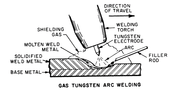
An arc welding process which produces coalescence of metals by heating them with an arc between a tungsten (nonconsumable) electrode and the work. Shielding is obtained from a gas or gas mixture.
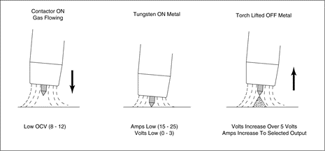
Lift Start was developed to provide a positive means of starting the Gas Tungsten Welding arc without high frequency. High frequency energy has been a very effective method of initiating the arc, but in some cases interferes with computerized equipment. In an effort to solve this problem, other means to start the arc were needed. Capacitor discharge circuits have been used, but they also produce radio frequency interference. Also, both high frequency and capacitor discharge circuits are limited to relatively short torch lead lengths.
Lift Start GTAW is not the same as “Scratch Tig”’ which results in rapid deterioration of the tungsten. Lift Start works quite differently. Lift Start circuitry permits the tungsten electrode of the GTAW torch to be placed precisely at the start of the weld, without damage to the tungsten or base metal. When the tungsten contacts the metal, the power supply limits it’s output to a very low preset value. The welding arc does not come on until after the tungsten is withdrawn from the metal. The power supply then automatically adjusts it’s output to the selected welding amperage. Lift Start may be used with AC or DC operation and may be used with torch leads up to 25ft.
Connect the TIG torch to the – / TORCH terminal and the work lead to the + / WORK terminal for direct current straight polarity. Direct current straight polarity is the most widely used polarity for DC TIG welding. It allows limited wear of the electrode since 70% of the heat is concentrated at the work piece.
PFC is the acronym for power factor correction.
In laymen’s terms a welding machine with PFC will use less input current than a welding machine without PFC for the same output current setting. PFC is very helpful when operating on standard 115vac circuits. For example, lets say a welding machine without PFC operating on a 20 amp 115vac circuit may only be able to produce 100 amps of output current without tripping the wall circuit breaker, but a welding machine with PFC operating on the same 20 amp 115vac circuit could produce 125 amps of welding output without tripping the wall circuit breaker. Big advantage when using a 1/8″ welding electrode that operates from 110 – 120 amps DC. The welding machine with PFC can perform a weld with this electrode where the welding machine without PFC cannot without tripping the wall circuit breaker.
Power quality is essential for efficient equipment operation, and power factor contributes to this.
Power factor is the measure of how efficiently incoming power is used in an electrical installation. It is the ratio of active to apparent power, when:
The power triangle:

Poor power factor (for example, less than 95%) results in more current being required for the same amount of work.
Power factor correction (PFC) aims to improve power factor, and therefore power quality. It reduces the load on the electrical distribution system, increases energy efficiency and reduces electricity costs. It also decreases the likelihood of instability and failure of equipment.
Power factor correction is obtained via the connection of capacitors which produce reactive energy in opposition to the energy absorbed by loads such as motors, locally close to the load. This improves the power factor from the point where the reactive power source is connected, preventing the unnecessary circulation of current in the network.


The selection of PFC equipment should be done according to the following four-step process, by persons with the relevant skills:
Step 1: Calculation of the required reactive power
The objective is to determine the required reactive power (Qc (kvar)) to be installed, in order to improve the power factor (cos φ) and reduce the apparent power (S).

Qc can be determined from the formula Qc = P (tan φ – tan φ‘), which is deduced from the diagram.
The parameters φ and tan φ can be obtained from billing data, or from direct measurement in the installation.
Step 2: Selection of the compensation mode
The location of low-voltage capacitors in an installation can either be central (one location for the entire installation), by sector (section-by-section), at load level, or a combination of the latter two.

In principle, the ideal compensation is applied at a point of consumption and at the level required at any moment in time. In practice, technical and economic factors govern the choice.
The location is determined by:
Step 3: Selection of the compensation type
Different types of compensation should be adopted depending on the performance requirements and complexity of control:
Step 4: Allowance for operating conditions and harmonics
Operating conditions have a great impact on the life expectancy of capacitors, so the following parameters should be taken into account:
Some loads (variable speed motors, static converters, welding machines, arc furnaces, fluorescent lamps, etc.) pollute the electrical network by reinjecting harmonics. It is therefore also necessary to consider the effects of these harmonics on the capacitors.
Savings on the electricity bill
Power factor correction eliminates penalties on reactive energy, decreases demand on kVA, and reduces power losses generated in the transformers and conductors of the installation.
Increased available power
Fitting PFC equipment on the low voltage side increases the power available at the secondary of a MV/LV transformer. A high power factor optimizes an electrical installation by allowing better use of the components.
Reduced installation size
Installing PFC equipment allows conductor cross-section to be reduced, as less current is absorbed by the compensated installation for the same active power.
Reduced voltage drops
Installing capacitors allows voltage drops to be reduced upstream of the point where the PFC device is connected, therefore preventing overloading of the network and reducing harmonics.
Tweco 11 series on the 200MF and 14 series on the 250MF.
Yes, See Brochure. We offer a Spool gun for the 200MF and 250MF. It cannot be attached to any other units.
A optional TIG Torch is available with standard off the shelve 10N series consumables. See Brochure for details. You can also use any Air Cooled TIG Torch that has a Dinse 50mm power plug and gas valve.
115vac and 230vac Single Phase.
Yes, For an explanation of PFC see FAQ Support Topic “Power Factor Correction – What is it? Why is it required? How is it Achieved?”
It comes down to cost. To run E6010 electrodes must have a big inductor and suitable software. This added circuitry is needed because E6010 does not contain potassium in the flux. Potassium helps to stabilize the arc. It will run E6011 just fine.
A optional TIG Torch is available with standard off the shelve 10N series consumables. See Brochure for details. You can also use any Air Cooled TIG Torch that has a Dinse 25mm power plug and gas valve.
No, TIG Torch requires a gas valve with connection to shielding gas regulator.
No, The 140S does not have remote control functions.
115vac and 230vac Single Phase.
No, it does not. The 160S does have PFC.
It comes down to cost. To run E6010 electrodes must have a big inductor and suitable software. This added circuitry is needed because E6010 does not contain potassium in the flux. Potassium helps to stabilize the arc. It will run E6011 just fine.
115vac and 230vac Single Phase.
Yes, you can run 6010 electrodes.
208-230 Single Phase, 208-230,460 three phase.
Yes, you can run 6010 electrodes.
208-230 Single Phase, 208-230,460 three phase.
No, the SANMIG 400M does not include MIG Pulse. For MIG pulse purchase our 400MP.
Yes, you can run 6010 electrodes.
208-230 Single Phase, 208-230,460 three phase.
Yes, The 400MP has MIG pulse built in.
Yes, you can run 6010 electrodes.
Description and general setting for Pulse TIG welding.
An arc welding process which produces coalescence of metals by heating them with an arc between a tungsten (nonconsumable) electrode and the work. Shielding is obtained from a gas or gas mixture.
Lift Start was developed to provide a positive means of starting the Gas Tungsten Welding arc without high frequency. High frequency energy has been a very effective method of initiating the arc, but in some cases interferes with computerized equipment. In an effort to solve this problem, other means to start the arc were needed. Capacitor discharge circuits have been used, but they also produce radio frequency interference. Also, both high frequency and capacitor discharge circuits are limited to relatively short torch lead lengths.
Lift Start GTAW is not the same as “Scratch Tig”’ which results in rapid deterioration of the tungsten. Lift Start works quite differently. Lift Start circuitry permits the tungsten electrode of the GTAW torch to be placed precisely at the start of the weld, without damage to the tungsten or base metal. When the tungsten contacts the metal, the power supply limits it’s output to a very low preset value. The welding arc does not come on until after the tungsten is withdrawn from the metal. The power supply then automatically adjusts it’s output to the selected welding amperage. Lift Start may be used with AC or DC operation and may be used with torch leads up to 25ft.
Connect the TIG torch to the – / TORCH terminal and the work lead to the + / WORK terminal for direct current straight polarity. Direct current straight polarity is the most widely used polarity for DC TIG welding. It allows limited wear of the electrode since 70% of the heat is concentrated at the work piece.
For Aluminum MIG Welding we offer our 400M or 400MP with our Sky 4HD Wire Feeder and Binzel PPI Push Pull MIG Gun or with the MK Python System.
See Brochures for ordering information.
Binzel PPI Push Pull MIG Gun Option.